Single Phase Smart Electricity Meter
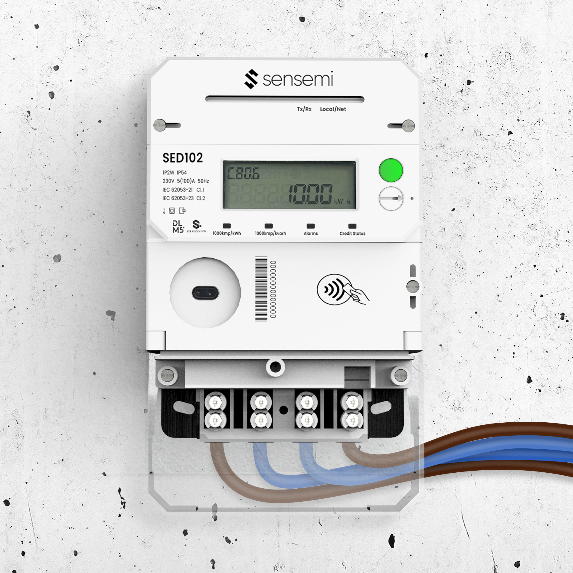
The SED102 Smart Electricity Meter supports flexible communication with up to three modules for seamless smart metering integration.
Features
bolt
Single phase, 230 V · 5 A basic, 100 A max current
verified
Class 1 active (IEC 62053-21) · Class 2 reactive (IEC 62053-23)
dialpad
STS prepayment · 12-key keypad with audible feedback
cell_tower
CAT.1 + 2G remote communication · RS485 and optical port
Everything you need to know
Open each section for features, connectivity, standards and technical data.
Download Brochure01Main FeaturesMain Features
Front View Description
monitor
Display
The digital display on the front cover provides real-time information such as energy consumption, voltage, and current.
touch_app
Data Query Button
A button is included for users to query or cycle through different data on the display. This can help users’ access additional information or navigate the meter's menu.
info
Meter Information
Important meter information is printed on both the front cover and the module door. This could include details like the meter's serial number, model, and other relevant specifications.
touch_app
Program Button
There is a sealable demand button that allows for demand reset. The sealable design ensures that the settings remain secure and tamper resistant.
Major Application
The single-phase SED102 smart electricity meter has several major applications:
dialpad
Keypad and Button Input Unit
The inclusion of a keypad and button input unit allows for user interaction. Users can input commands, query data, or navigate through the meter's features using the keypad and buttons.
memory
Protective PCB Board
The electric meter's PCB (Printed Circuit Board) is coated with protective paint. This protective layer serves as a barrier against moisture, dust, and pests, ensuring the durability and reliability of the meter in various environmental conditions. The SED102 smart electricity meter offers a range of advanced features for communication, control, and measurement, making it suitable for modern energy management systems. These capabilities contribute to more efficient energy usage, billing, and overall utility operations.
compare_arrows
Load Switch and other auxiliary equipment
The load switch may enable remote control of electrical loads, contributing to demand response and load management strategies.
avg_time
Measurement Unit
The meter includes a measurement unit responsible for accurately measuring electricity consumption. This unit ensures precise data collection for billing and monitoring purposes.
123
Display Unit
A display unit is integrated into the meter, providing real-time information about energy consumption, voltage, and current. Users can easily access and monitor their electricity usage.
nest_clock_farsight_analog
Real-Time Clock Unit
The meter incorporates a real-time clock unit, enabling it to timestamp data and events accurately. This feature is crucial for time-of-use billing and tracking consumption patterns over specific time periods.

Features
The characteristics of the single-phase SED102 smart electricity meter are as follows:
dialpad
Plug-In Input Module (Keypad/NFC)
It features a plug-in input module, supporting either a keypad or Near Field Communication (NFC) technology for user interaction and data input.
settings_applications
Software Upgrade locally or remotely
The meter supports software upgrades, which can be performed either locally or remotely. This ensures that the meter can stay up-to-date with the latest features and security enhancements
account_tree
Internal Magnetic Latching Relay
An internal large capacity magnetic latching relay is included, supporting load control through parameter configuration or communication commands. This allows for efficient management of electrical loads.
flash_on
Active Energy Accuracy
The meter has a high level of accuracy for active energy measurement, complying with Class 1 standards as per IEC 62053-21.
avg_time
Wide Range of Current Measurement
The meter offers a wide range of current measurement, covering starting current to the maximum current, with accurate readings.
123
Data Display
It provides data display functionality, including information presented on the meter's LCD display. Users can access real-time data about energy consumption, voltage, current, and more.
grid_on
Grid Parameter Detection
The meter can detect grid parameters in real-time, including power, voltage, current, power factor, etc. This information is crucial for monitoring and managing the electrical grid.
battery_android_frame_full
Changeable Battery
The meter supports a changeable battery, ensuring that the display remains functional even in the absence of power. This is important for continuous monitoring and data retrieval.
nest_clock_farsight_analog
Real-Time Clock
A real-time clock is integrated into the meter, providing accurate time stamping for data and events.


02Communication TechnologiesCommunication Technologies
settings_input_component
Optical Communication Interface
An optical communication interface is present for data exchange. This interface might be used for data reading, configuration and firmware upgrade.
nest_remote_comfort_sensor
Remote Communication and Control
The meter supports remote communication and control using a CAT.1+2G module. This enables two-way communication with utility providers or other relevant entities.
info
Digital Medium for Information Exchange
The meter utilizes digital media for information exchange. This likely involves the use of digital signals or protocols for transmitting and receiving data, enhancing the efficiency and accuracy of communication.
communication
Infrared Communication
Infrared communication capability is included, allowing the meter to communicate with other devices or systems using infrared signals.
nest_remote_comfort_sensor
Plug-In Remote Communication Module
The meter supports a plug-in remote communication module, allowing for flexible communication options and easy upgrades
lock
Communication Data Encryption
Communication data encryption is implemented to ensure highly reliable and secure communication between the meter and external systems.
03Standards and CompliancesStandards and Compliances
forum
DLMS/COSEM Specification
The meter complies with the DLMS/COSEM (Device Language Message Specification / Companion Specification for Energy Metering) standard. This ensures full interoperability with head-end systems and other compliant devices, enabling standardized data exchange, remote configuration, and secure communication across smart utility networks.
workspace_premium
STS Standard
The meter complies with the STS (Standard Transfer Specification) standard, which is often used for secure and standardized token-based prepayment systems. These characteristics collectively contribute to the functionality, reliability, and versatility of the SED102 smart electricity meter in various applications, offering advanced features for both users and utility providers.
Standards
| IEC Standard | Description |
|---|---|
| IEC62053-21 | Static meters for active energy (class 1) |
| IEC62053-23 | Static meters for reactive energy (class 2) |
| IEC 62052-11 | Electricity metering equipment (a.c.) – General requirements, tests and test conditions – Part 11: Metering equipment |
| IEC62053-31 | Pulse output devices for electromechanical and electronic meters |
| IEC60695-2-11 | Specifies a test method on an end product. It is intended to simulate the effects of thermal stresses produced by an electrically heated source to represent a fire hazard. This test method is used to check that, under defined test conditions, an end product exposed to an electrically heated source has either a limited ability to ignite or, if it ignites, a limited ability to propagate flame. |
| IEC 62056-21c | Electricity metering – data exchange for meter reading, tariff and load control – Part 21 Direct local data exchange |
| IEC62056-42 | Electricity metering – Data exchange for meter reading, tariff and load control – Part 42: Physical layer services and procedures for connection-oriented asynchronous data exchange |
| IEC62056-6-1 | Electricity measurement – meter reading, tariff control and load control data exchange: OBIS |
| IEC62056-6-2 | Electricity measurement – meter reading, tariff control and load control data exchange: Interface |
| IEC62056-46 | Electricity measurement – meter reading, tariff control and load control data exchange: HDLC protocol data link layer |
| IEC62056-5-3 | Electricity measurement – meter reading, tariff control and load control data exchange: COSEM application layer |
| IEC62056-4-7 | Electricity measurement – meter reading, tariff control and load control data exchange: IPv4 network COSEM transmit |
| IEC62055-31 | Payment systems - Part 31: Particular requirements - Static payment meters for active energy (classes 1 and 2) |
| IEC62055-41 | Electricity metering – Payment systems – Part 41: Standard transfer specification (STS) – Application layer protocol for one-way token carrier systems |
| IEC62055-51 | Electricity metering – Payment systems - Part 51: Standard Transfer Specification – Physical Layer Protocol for one-way numeric and magnetic card token carriers |
04Technical DataTechnical Data
Connection
The wiring diagram is laser printed on the terminal cover of the meter. This provides users with clear guidance on how to connect the meter according to their specific requirements. The Material used for the Microcontroller Unit (MCU) enclosure has good dielectric and mechanical strength with the minimum thickness of 2.0mm, ensuring durability and robustness. The material used in the MCU enclosure complies with the IEC 60695-2-11 standard, which involves the glow wire test. This standard assesses the fire hazard of electrical equipment by exposing it to a simulated ignition source. These specifications reflect a focus on safety, durability, and compliance with industry standards for the materials used in the construction of the smart electricity meter. The inclusion of the wiring diagram on the terminal cover makes the installation process user friendly and efficient, allowing customers to follow clear instructions for proper connection.

Auxiliary Terminal Description and Electrical Characteristics

Mechanical Structure
Material Used
layers
The meter base and cover are made of non-metallic material.
water_drop
The material is non-hygroscopic (does not absorb moisture).
wb_sunny
It is UV stabilized, which means it can withstand exposure to sunlight without significant degradation.
local_fire_department
The material is flame retardant, offering safety in the event of a fire.
auto_awesome
It is polished, providing a smooth and aesthetically pleasing surface.
shield
The material has high impact-resilience, indicating its ability to absorb and withstand impacts without breaking.
cleaning_services
It has low dirt absorption properties, making it easier to clean and maintain.
verified
The terminal block material passes ISO 75-1, the standard for testing the temperature behaviour of plastics.

Dimensions

Terminal
The meter is for front projection mounting. The terminal holes and screws are moving cage type.

Technical Parameters
| Parameter | Specification |
|---|---|
| Reference voltage | 230V |
| Working voltage | 0.6Un~1.2Un |
| Reference current | 5A |
| Maximum current | 100A |
| Accuracy class | Class 1 (Active); Class 2 (Reactive) |
| Pulse constant |
Active: 1000 imp/kWh Reactive: 1000 imp/kvarh |
| Frequency | 50Hz ±5% |
| Temperature |
Working temperature range: -40℃~+70℃ Store temperature: -40℃~+70℃ |
| Humidity | ≤95% |
| Altitude | 3000m |
| Atmospheric pressure | 63kPa-106kPa |
| Relay |
Maximum switch current: up to 120A Short circuit <= 10ms: 3600A Mechanical life: >= 100000 OPS Electric life: >= 10000 OPS |
| Wiring |
LNNL Connection for overhead and underground system |
| Voltage circuit consumption | ≤ 1W and 5 VA @ 230V |
| Current circuit consumption | 2VA @ 5A, 50Hz, 30°C |
| Starting current | 4‰ Ib |
| Protection degree | IP54 |
| Display format |
LCD supports 8 digits Auto scroll mode, manual display mode, power off display mode |
| Button |
The upper button is used for manual display The lower button (sealed) is used for Demand reset |
| Keyboard | 12 keys with audible feedback, meter still IP54 Compliant |
| PCB Board | Conformal coated |
| Average Service life |
≥15 years (Except for the battery, the average life of battery is not less than 10 years) |
| RTC Accuracy | 0.5s/day at reference temperature, comply with IEC 62054-21 |
|
Communication interface (optional) |
Optical: read and configure the meter locally Remote communication: RS485 / CAT.1+2G |
| Backup-power supply | Internal battery or Extend Replacement Battery. Support RTC, LCD with backlight during AC power off. |
| Measurement | One element |
| Electrostatic Discharge Immunity |
Contact Discharge: 10KV Air Discharge: 16KV |
| HF Electromagnetic Field Immunity |
80 MHz – 2 GHz, 10 V/m 2 GHz – 6 GHz, 3 V/m |
| Fast Transient Burst Immunity |
4 kV on the power ports 2 kV on the signal ports |
| Surge Immunity |
4 kV between line and earth 2 kV between lines |
| Insulation Strength |
4 kV RMS during 1 min between measuring circuits and current circuit 2 kV RMS during 1 min between measuring circuits and communication circuit |
| Impulse Voltage | 6 kV (1.2/50 μs) |
Case Components
The case includes various components that are visible from the outside.